The (mostly) green shoots of my career
The first sections of widening on the M25 motorway also saw the first use of steep reinforced soil slopes on the UK motorway network providing a great opportunity to demonstrate the many benefits of reinforced soils. Over 30 years on from their construction the majority of the public are probably still unaware of the geosynthetic structures they view in the daily traffic jams.
As a fresh graduate my first position came in answer to an advert for a graduate engineer to work on the design and construction of reinforced soil slopes, preferably French speaking and with experience of reinforced soil design which as a graduate of Grenoble University at the outset of the Erasmus scheme saw me tick both boxes and took me to the South East of the UK to join Comtec UK ltd to work on the widening of the first 3 sections of the M25 motorway from junctions 15-16, 7-8 and 8-10 for Tarmac, Laing and Mowlem respectively.
This was two years before the publication of HA68/94, the first UK design method and guidance for reinforced soil slopes which specifically addressed the issues that specifically affect steep slopes rather than vertical MSE walls. Trust had to be gradually built both from a design perspective that utilised and compared all available methods at the time from Jewell’s log spiral analyses to multi part wedge analyses that mirrored the parallel development of HA68/94 by GCG.
Given the notoriously slow nature of the traffic on the section of the M25 in question the slopes were built under the watching eye of both the engineering community and the public. The pace of the observer was particularly unnerving when they could practically watch as blades of grass grew or, in some cases, died.
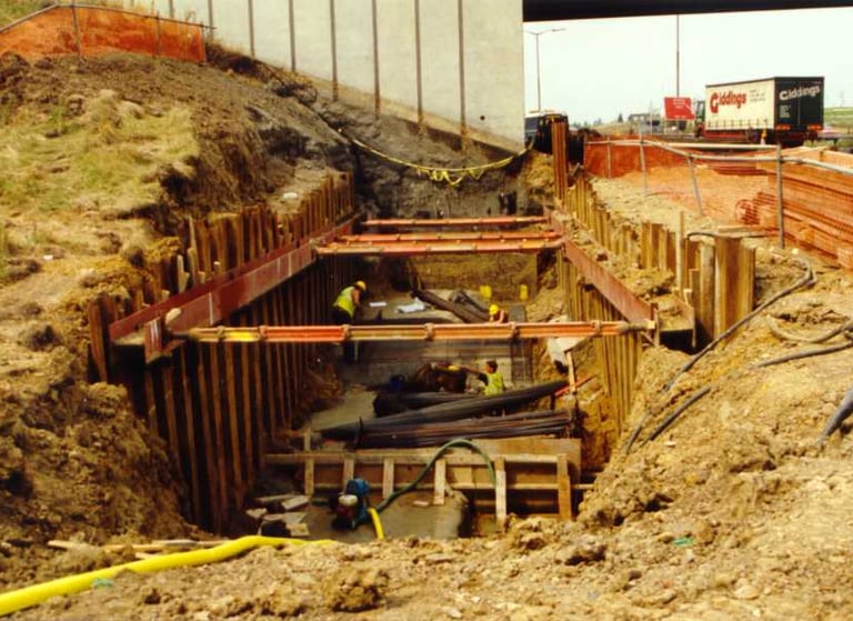
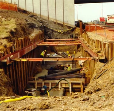
The conforming solution for the retaining walls on the scheme consisted of reinforced concrete cantilever walls, due to the low shear strengths of the clays overall stability became an overriding concern however and despite the vertical wall face required to facilitate the 4m widening only being 2-3m in height, the toe depth required to satisfy global stability concerns was up to 3m. This deep foundation provided issues not only in terms of the temporary trench stability which required sheet piling and strutting for the erection of the formwork, steel fixing and concrete pour but where the toe depth cut into the water bearing gravel layers de-watering measures were required until the wall had been completed.
Soil nailing and vertical Reinforced Soil walls with block or panel facings were considered as possible alternatives but with the time available to consider alternatives and gain design approval, nailing and vertical solutions which would have required a full Technical Approval were considered to pose too much risk of a delay whereas steep reinforced slopes up to 70o could be submitted with Geotechnical Certification only which would be substantially quicker whilst requiring a less onerous safety factor of 1.3 for global stability rather than the 1.5 factor used for structural solutions. There was still a reluctance to commit entirely to the RSS solution however with the southbound carriageway commencing construction of the conforming RCC walls and the northbound carriageway being submitted for certification of the alternative.
On the first contract, the design submission faced the major hurdle of satisfying the Engineer, Sir William Halcrow & Partners, at a time when there was no Department of Transport approved design method. The initial design proposal for the RSS from specialist subcontractor Comtec UK Ltd utilized a STRU model developed by Peter Steiner and Rudolf Rüegger, a two part wedge mechanism with the interwedge boundary inclined at the same angle as the tails of the reinforcement. This design was checked by Jerry Love of the Geotechnical Consulting Group who at the time was finishing drafting HA68/94 the guidelines for the design of steep slopes, his revised proposal followed the vertical interwedge boundary with a modified interface sliding coefficient at the wedge boundary.
On the first contract, the Engineer was reluctant to adopt these new methods so a hybrid design solution was used with a Modified Bishop slip circle analysis being used to determine the required depth and length of the lowest layer of reinforcement with a non-circular Janbu analysis similar to Jewell’s charts being used to check potential slips between or along the reinforcement layers within the slope. Following the publication of HA68/94 at the end of the construction of Junctions 15-16 the subsequent contracts adopted the newly approved two part wedge design method.
The initial proposal for the walls utilized a continuous filament, non-woven needle-punched geotextile as the reinforcement but the lack of an agrément[MF1] certificate forced a change to an approved woven PET geogrid with PVC coating as the principal reinforcement. Secondary half width layers of the non-woven were utilized as intermediates within the construction as the in plane wicking of water through the textile assisted greatly in the compaction of the cohesive fill materials. The reinforcements were layered up to the face of the wall but not wrapped around, a separate 1.5m width of woven polyester vegetation fabric was used at the face inside a braced steel mesh sacrificial formwork which enabled rapid construction up to 120m2 per day at each work front, accurate face alignment and minimal deformation during compaction of the fill material.
When working with heavy cohesive materials like the London and Gault clays compaction with a conventional smooth roller serves only to iron the surface and push a film of water across the clay which is reabsorbed once the compactive effort has passed, utilizing a 1.5T sheepsfoot roller provided a combination of kneading and vibratory compaction to the clay which along with the intermediate layers of non-woven fabric helped eliminate moisture and ensure proper compaction was achieved, verified on site by sand replacement tests and nuclear densometer.
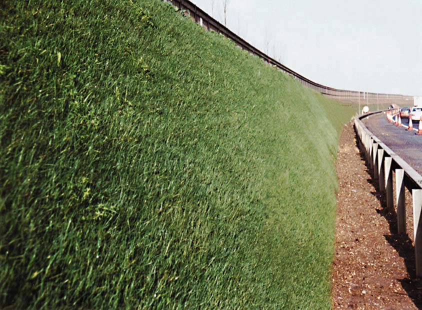
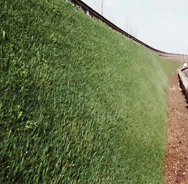
The finish of these steep slopes was to consist of a blend of grasses established through hydraulic seeding of the finished slope face with the standard highways blend of a mix of fescues and perennial rye grasses, hydroseeding and initial maintenance of the slopes was all carried out by Comtec, the installation and design subcontractor for the slopes. Initially the vegetation took very well within the hydroseeding mulch on the face of the walls with a healthy sward of the rye grasses establishing in the first month or two post seeding.
In areas the vegetation suffered a total die back which did call into question the potential for these solutions and the longevity of the facing materials. The vegetative failure was not however confined purely to the RSS slopes, with adjacent 1:3 slopes suffering similar die back which was determined to be caused by high toxicity levels due to the presence of heavy metals in one of the topsoil supplies. Since the topsoil was encapsulated within the face of the RSS slopes replacement was not a viable option and the slopes were treated to a series of flushings with a gypsum solution and hand planting with rhyzomes of hardy cooch grass to draw out the toxins over a couple of growing seasons prior to removing the hydroseed cake mulch that was protecting the face from UV exposure and eventual reseeding when the toxicity levels had fallen.
In other areas localized patchy growth and seasonal dieback occurred over the first 2 to 3 years which was maintained by the sub contractor through combinations of adjusted seed blends, localized irrigation and shade netting to ensure the nursery crops of grasses firmly established.
30 years on the vegetation on the slopes, whilst not 100% consistent is still following the same natural cycles of spring and autumn greenery and summer brown out that affects the neighboring shallow slopes. The original species selection has led to limited maintenance requirement except in areas where invasive local groundcover plants have taken over the faces and need to be trimmed back to maintain sight lines.
Having a direct comparison against the conforming alternative on the opposite carriageway of the jn15-16 contract made many of the benefits of the RSS solution stand out. In terms of the speed of construction the northbound reinforced soil slopes were completed in 10 weeks compared with 7 months for the RC walls where the extensive temporary works and dewatering associated with the RC walls as well as the need to export the cut slope material from site and reimport fill to the wall later pushed their construction cost to over 4 times that of the RSS solution.
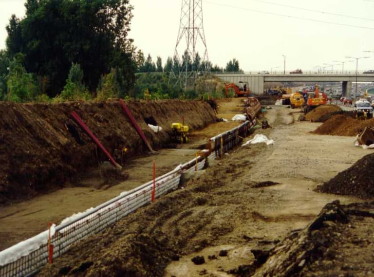
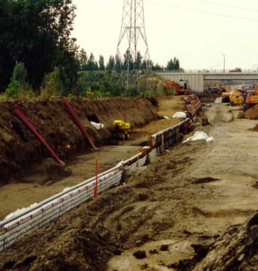
Comparison of 1m deep RSS foundation vs 3m deep RC foundation
The increased construction speed and elimination of the temporary works and material import increased site safety and reduced the risk to the public by ensuring the traffic controls were removed earlier. At the time, the green finish of the walls was about as far as the environmental concerns went however the work done by the EAGM, WRAP and others in calculating the whole life carbon footprint reductions achieved by these techniques is now widely recognized.
Much of the environmental and cost benefit came from the reuse of poor quality site won material rather than the importation of engineered fills; the proper combination of grids and non-wovens, installation of drainage, effective compaction and a facing system robust enough to withstand the compactive effort without undue deformation are all key to the schemes’ continuted success.
Whilst the vegetated finish of steep slopes is often seen as an afterthought by engineering contractors the slope finish is what the public will eventually judge these structures by so getting it right is essential. The harsh environment posed by steep slopes immediately adjacent to the live carriageway should be carefully considered in designing the vegetation scheme. Wall orientation will determine the amount of moisture and light the face will get which can dramatically affect the success of the initial seeding, particularly on south facing slopes in the northern hemisphere. Proximity of the traffic to the face can lead to higher wind drag on the face which leads to more rapid drying as well as the contamination of the face with spray and particularly with road salts in the winter months.
Good quality topsoil should be used within the front 150-300mm of the face of steep slopes and should be tested to ensure there are no toxins present. Hydroseeding should be carried out as soon after construction as possible to prevent the topsoil from drying out and shrinking away from the vegetation fabric, where walls have to stand prior to seeding then the face should be weeded and thoroughly watered prior to seeding.
The seed mix should be considered to suit the environment but typically a blend of hard fescue, sheeps fescue and red fescue provides a consistent growth and produces a short sward which will require minimal maintenance and have good drought resistance. Rye grass is often specified due to the rapid growth which gives a quick greening but its length and sensitivity to drought can cause it to die back and form an impenetrable matting on the face which kills off other species whilst its rapid growth tends to strip the topsoil of nutrients and starve the slower hardy species. Other species such as salt marsh grass, meadowgrass or creeping bent can be added to provide a more robust salt tolerance if required whilst clover can be added to increase nitrogen fixity in the soil ensuring better nutrition for the other species. Where the environment is too harsh for grasses the sensible alternative is to cover the face by hand planting ground cover shrubs which can either be ornamental or use native species which may be better suited to the location.
With over half of the 60 year design life of these structures gone their finish looks remarkably unaltered and maintenance, beyond the initial vegetation establishment, has not been a major issue and even where one of the slopes was impacted by a heavy goods vehicle the repairs to both the slope and the truck were minimal which would not have been the case had the truck hit a reinforced concrete wall. The traffic still moves slowly through these sections of the M25 but at least it gives me plenty of time to review my first project on a regular basis and reflect proudly on reducing the cost of the works to 1/3 of the conforming solution with construction in half the time and with a significantly reduced carbon footprint.
DW Geotech
QA/QC for geosynthetic systems and retaining structures from desk study to site installation.
SYSTEMS
Overview
About
Services
Enquiry
CONTACT DETAILS
info@dwgeotech.com
Project Enquiries: +44 7575 301375
Tunbridge Wells UK
(C) 2026 DW Geotech-Ensuring geosynthetic performance in field conditions.
INDEPENDENT GEOSYNTHETIC ADVICE